
|
Flash Photomicrography.
Electronic Flash as a Light Source for Photography through the Microscope. |
Page 4 of 7 |
|
|
Flash Photomicrography.
Electronic Flash as a Light Source for Photography through the Microscope. |
Page 4 of 7 |
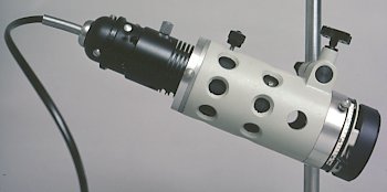 The design of this flashlamp is both determined by, and made possible by, the nature of the light sources involved.
The light from the filament modelling lamp must be re-imaged in the plane of the flashtube. It could not work the other way around as light from the flashtube could not pass without obstruction through the filament of a tungsten lamp. Determining the exact position of the filament image requires careful measurement, as it determines the place where the 1/2" hole must be drilled in the lamp housing to accommodate a flashtube located at the mutual focus of the condenser system elements, and holes once drilled cannot be moved. The optical quality of the condenser lenses used is of prime importance, not so much for the flash as for the modelling source, which must pass through three such condensers in order for its image to reach the plane of the substage condenser diaphragm. Any imperfections in the condenser elements will thus be amplified in terms of the consequent distortion to the filament image. These distortions result in an unevenly illuminated microscope field. Not only does this make the lamp unpleasant to use, it provides a poor approximation to the image which will be captured by the flash. That the flash image will be of better quality in terms of evenness of illumination is some compensation -- this is more or less guaranteed by extended size and intrinsically structureless nature of the xenon gas plasma discharge, and the fact that it is imaged only by a single condenser.  Single aspheric lenses are the best suited for the condenser elements.
These are usually corrected for spherical aberration at infinite conjugates The space between the elements is not critical and offers an ideal place for a blue colour conversion filter to approximate the tungsten light to that of the flash. It is also the ideal place for introducing a slight degree of diffusion to minimize any distortion of the filament image which may be caused by cumulative errors in the aspheric surfaces. The trade-off for introducing a diffuser is of course reduced modelling light intensity. The next important consideration is that the modelling filament image should be equal in size to the bore of the flash tube -- or more accurately, to the width of the gas discharge, which does not quite fill the tube. This is necessary to ensure that images set up using the modelling source will be replicated by the flash exposure. The third condenser unit (8) has provision to hold filters (16) which further modify or attenuate the light from the lamp, and are sufficiently far in front of the lamp for any dust which settles on them to be out of focus in a Köhler setup. 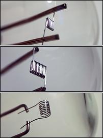 The shape of the lamp filament is also important. Clicking the link images to the right will produce an enlarged image of each filament.
The Philips 15W lamp (top) and Olympus 30W lamp (middle) have the tightly wound flattened square grid ideal for microscope lamps. The cylindrical coil filament (bottom) is from a Russian microscope lamp and both the looser winding and the depth of the coil pose difficulties in terms of obtaining an evenly illuminated field at the microscope. It is also important that the glass of the lamp envelope is of uniform thickness and curvature at the end between the filament and the lamp condenser to avoid lensing effects which distort the filament image and result in non-uniformity of illumination at the specimen plane. The distance of the filament from the end of the envelope will determine the minimum focal length condenser with which the lamp can be used. The factors to be considered in the choice of condenser and source are dealt with more fully in the article on the design of microscope lamps for Köhler illumination. In order that the modelling light source accurately represents the image which will be captured by the flash, its size relative to the width of the flash discharge is of critical importance. 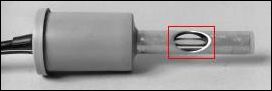 Click on the link to the right to see aerial images of two tungsten lamps projected into the plane of the flashtube by the double condenser system of the lamp shown at the top of the page.
The pictures were taken through the microscope using a photomicrographic camera. The lamp condenser was removed and the substage condenser refocused to image the flashtube. It will be seen that the 30W lamp filament is the same vertical height as the flash discharge, making it the ideal modelling source. It will also be seen that only light generated in the portion of the flashtube corresponding to the area of the filament image can be utilized by the microscope -- the rest is wasted. Therefore it is not the total light output of the flashtube which is important to film exposure, but the intensity of the discharge in that portion of the tube which is imaged into the microscope substage condenser. This suggests that a flashtube of much shorter arclength would be better suited to the needs of the photomicrographer, allowing a discharge of the required intensity to be generated with proportionally reduced power, and therefore allowing faster flash recycle times. For a more detailed consideration of these factors, see the article on Electronic Flash as a Light Source for Cinemicrography (in preparation). The next practical step is the determination of exposure for the film stock in use.
|