
|
Flash Photomicrography.
Electronic Flash as a Light Source for Photography through the Microscope. |
Page 3 of 7 |
|
|
Flash Photomicrography.
Electronic Flash as a Light Source for Photography through the Microscope. |
Page 3 of 7 |
The diagram below shows the optical arrangement neccessary to ensure that both the modelling source and the flash tube will have the same optical relationship to the microscope optics when the lamp is used in a Köhler illumination setup. Click the link if you feel the need to go to the tutorial on setting up Köhler illumination. The photograph below the diagram shows the components of a lamp constructed to implement this optical arrangement. The numbers in the diagram relate to the corresponding components in the lamp.  Optical diagram of microscope flash lamp (not to scale).
A grid-filament tungsten filament bulb (1) in a centreing/focusing lamp housing (2) is held with clamping screws (3) to a sleeve (4) containing a double condenser system, consisting of two identical aspheric lenses (5 and 6) with their strongly curved surfaces facing. This arrangement relays an image of the lamp filament to the plane of a flashtube centred in a cylindrical holder (7). A third condenser combination (8), consisting of another aspheric lens (9), a field lens (10) and an iris diaphragm (11) projects exactly coincident images of both flash tube and modelling filament into the plane of the microscope substage diaphragm (12). 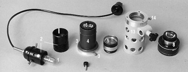 Components of the microscope flash lamp.
All components are assembled in the body of a Russian microscope lamp (13). The focal length of the field lens (10) is 250mm, that being the lamp distance for which most microscope substage condensers are corrected. It also enables focus to be achieved with the flash tube at the principal focus of the aspheric element, since aspherics are corrected for spherical aberration at infinite conjugates. The aspheric lenses used in the condensers (and their mounts) were obtained by dismantling three Russian aplanatic substage condensers, the lower elements of which were well corrected, powerful aspheric lenses. At the time (1978), the entire condenser with supplementary lens in a fitted wooden box was cheaper than a single aspheric lens from the catalogues of optical suppliers. This is no longer the case, as suitable aspheric condenser lenses can be obtained from most suppliers for $25 - $30. A Russian microscope lamp was used for the main lamp body and stand. The centreing lamp housing was from a discarded Meopta substage lamp. The picture below is of the assembled lamp with the flashtube holder (7) in position. 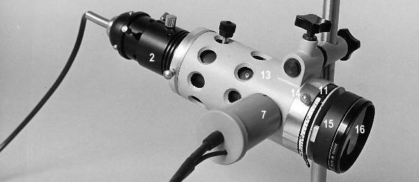 The assembled microscope flash lamp.
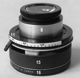
The centreing focusing modelling light housing (2) is shown fitted to the main lamp body (13). The third condenser assembly (8) is focused by a sliding action in a close-fitting sleeve, and clamped by means of the thumbscrew (14). The condenser is fitted with a threaded ring (15) which allows the addition of Nikon 52mm threaded filters, and is shown with a colour correcting gel filter (16) in position. 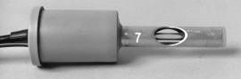 The flashtube holding module (7, left) is constructed from half-inch diameter aluminium tubing fitted to a 35mm film container which houses some peripheral electronics, including the flashtube trigger transformer. The smaller of the two cables is the synch. cable which connects to the photomicrographic camera.
The hole in the tube is cut away so as not to obstruct the large aperture cone of rays formed by the aspheric condensers.
The flashtube holding module (7, left) is constructed from half-inch diameter aluminium tubing fitted to a 35mm film container which houses some peripheral electronics, including the flashtube trigger transformer. The smaller of the two cables is the synch. cable which connects to the photomicrographic camera.
The hole in the tube is cut away so as not to obstruct the large aperture cone of rays formed by the aspheric condensers.
 The picture (left) shows details of the third lamp condenser assembly. The cylindrical body and the aspheric lens mount have been retained from the original Russian aplanatic condenser, and the diaphragm is from a Russian Abbe condenser. The grey part supporting the threaded filter mount is from the original Russian microscope lamp.
These components are currently available from suppliers of Russian microscope equipment, and represent a cheap and satisfactory solution to obtaining the mechanical and optical items needed to build your own lamp. Click here (later) for more detail on other components in the lamp construction. With a flashlamp of this design, it is certain that whatever lighting effects are achieved by the modelling light will be faithfully replicated in any picture taken by the flash. Here are a couple of example photomicrographs taken with the flashlamp -- an actively feeding rotifer in darkfield, and an actively feeding rotifer in brightfield -- both subjects that could not have been sharply imaged on the film used (Kodachrome 25) using a continuous light source. In practice, the flash exposure usually shows better evenness of illumination across the field than can be achieved with the modelling light. The reasons for this, with more detail on the optics involved, are dealt with next.
|