 |
Applied Microscopy. The Microscopy of Vinyl Recordings. Tracking the Vinyl Groove. |
Page 5 of 5 |
|
|
Applied Microscopy. The Microscopy of Vinyl Recordings. Tracking the Vinyl Groove. |
Page 5 of 5 |
 The reproduction of music from a vinyl disc depends upon the playback stylus maintaining contact with both walls of the groove even in the most heavily modulated (loudest) passages of the music, and at the highest frequencies captured in the recording, which produce the highest accelerations in the stylus tip.
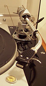
This page describes the function and setup of the "moving magnet" type of cartridge used in most record players. Once the cartridge, arm and turntable have been set up with due regard to factors such as turntable/arm geometry, arm resonance and stylus rake angle, the tracking ability (or traceability) of a stylus in the record groove depends on a number of factors: 1. Stylus tip mass. This is an odd concept in that the tip cannot be separated from the rest of the stylus/cantilever/magnet assembly. Obviously the less mass there is in the entire thing the better -- particularly at the stylus end where the movement is greatest. 2. The flexibility of the cantilever mount. The term used to describe this is compliance, and is the deflection at the stylus tip produced by a given force, usually measured in cm/dyne or µm/mN. The cantliever, itself very stiff, is mounted in a small ring of synthetic rubber, and the stiffness of this mount determines the compliance. Too stiff and the tracking ability is reduced -- not stiff enough and the cartridge will contact the record surface. 3. Tracking force. This is the force (usually in grams) with which the stylus contacts the record surface, and is set by adjusting the position of the counterweight of the pickup arm. Most moving magnet cartridges have a recommended tracking force in the range of 1 - 2 grams. 4. Bias. The geometry of a correctly set-up pickup arm (not discussed here) ensures that there is always a net force tending to make the stylus skip grooves and move towards the centre of the record. This is called bias, and must be compensated to ensure that the stylus bears with equal force on each wall of the groove. This can be done in various ways. The SME 3009 arm (pictured above) uses a graduated rear-projecting lever with a position-adjustable nylon thread attatched via a guide to a counterweight. Other makers employ spring-loaded or magnetic devices to achieve the same result. The picture below shows the parts of a cantilever assembly from a consumer-level Ortofon cartridge. The cantilever is the aluminium (or beryllium?) tube in the centre. It has been been bent and straightened, and the stylus tip has been removed in the same accident which prompted the (unsuccessful) straightening operation. 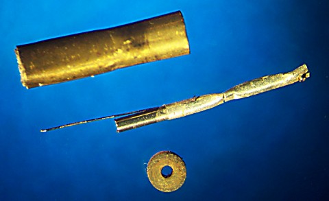
Parts of the cantilever assembly from an Ortofon cartridge. The synthetic rubber ring (below) grips the cantilever shaft, and the whole is fitted into the brass tube (above). The thin wire spring extending from the magnet end of the cantilever is attatched to the inside of the brass tube, and serves to damp or restrain the movement of the magnet. The brass tube is encased in a plastic moulding which slides the stylus into a mating slot in the cartridge body. 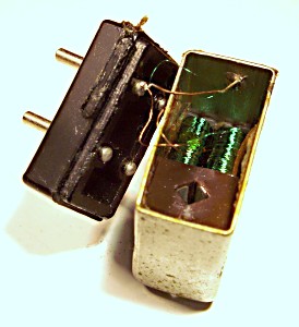
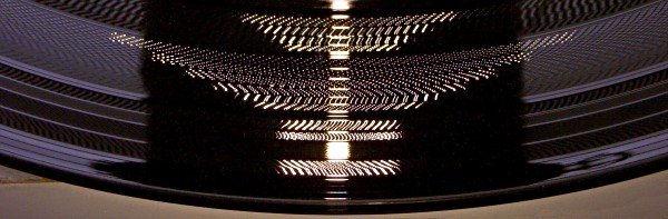
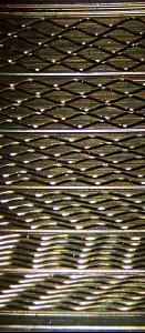
The picture on the right shows the internal construction of the cartridge for which the stylus was made. When the stylus assembly is pushed into position, the brass tube and the enclosed magnet are located inside the square hole (here viewed from the rear, connection-pins end) within the body of the cartridge. The pickup coils for the left and right channels with their associated pole-pieces extending into the square hole can be clearly seen. The fluctuating magnetic field produced by the magnet moving in sympathy with the grooves of the record generates a fluctuating electrical signal in the pickup coils. This signal is conducted by fine wires inside the pickup arm to the preamplifier of the record player amp. Whilst it is possible to set up a tone arm and cartridge in an approximate way by following the manufacturer's instructions and making adjustments until playback sounds OK, better quality equipment and high amplitude vinyl recordings require more precise methods. A test record of the kind shown below provides probably the most reliable method of quickly and simply achieving an optimum setting. The setup sequence consist of six tracks of a lateral cut 300Hz sine wave tone, each of about ten seconds duration, and increasing in amplitude from track 1 to track 6. In general, home consumer record decks will successfully track the first three tracks. Only the very best equipment, properly set up, will be able to track all six.
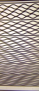
It will be seen that the places where the stylus undergoes the most rapid change of direction (greatest acceleration) is at the peak and trough positions in the wave form. There are two such positions in each cycle of the wave. At these positions, the stylus is most likely to lose contact with the walls of the groove -- in other words, the stylis tip will ride up one wall of the groove and bounce back and forth from one wall to the other as it passes from peak to trough. This is what is happening when we hear "distortion" in loud or high frequency passages of the reproduced sound. In the tracking test, the point at which this begins to happen is announced by an irregular high-pitched whine (buzzing) of about 600Hz becoming audible above the fundamental 300Hz tone of the test track, and is the sound of the stylus briefly losing contact with the groove wall at peak and trough. This sound is unmistakeable, and warns that the stylus will not cope at all with the next track in the test. Momentarily playing the next track will confirm this, and the arm should be lifted immediately to avoid damage to the test record. The 600Hz whine provides the means of adjusting the bias setting for the tracking force employed. When the bias is correctly set, the whine will sound equally in both left and right channels. The bias adjustment can now be made so that this is the case. This is best done using the track which produces the first audible distortion, and listening carefully to both channels whilst gently tapping the turntable to induce mistracking. Tracking may be enabled at the required amplitude level by increasing the tracking force. The most obvious consequence of this is increased wear on both record and stylus, but this is far preferable to allowing even the slightest amount of mistracking. In no case should the manufacturer's recommended maximum tracking force be exceeded, for this indicates that the fault lies elsewhere -- either a fault in the pickup arm or its alignment, or possibly insufficient compliance in the mounting of the stylus under test. Tracking becomes more difficult towards the centre of the record, where the speed of the record beneath the stylus is less than half the speed at the record's edge, and for any given frequency, the groove modulations are twice as closely spaced. Clean reproduction of high frequencies in this region is a particular challenge, and elliptical styli are much better suited to the task than the cheaper spherical styli. Accordingly, this test record has another set of 300Hz tracks towards the centre of the disc which provide the final, definitive adjustment. A brief trawl through Google in search of test records indicates that there are a small number of companies still offering test records of various descriptions which appparently have setup tracks equivalent to those on the HiFi for Pleasure disc used in the above discussion. This disc is now over twenty five years old, has suffered little wear, and is still used on an irregular basis for identifying anomalies in the system, setting up new cartridges, and checking that components are still correctly adjusted. Well worth the purchase price. Uploaded 3rd. August, 2005. |