
|
Applied Microscopy.
Mosquitoes Transmitting Microfilariae. Details of the Optical System. |
Page 2 of 2 |
|
|
Applied Microscopy.
Mosquitoes Transmitting Microfilariae. Details of the Optical System. |
Page 2 of 2 |
Since the operator must concentrate upon an image whose composition is controlled by one hand, and whose focus is controlled by the other, manually firing a camera shutter is out of the question. The replacement of the manually operated Zeiss camera body with the footswitch operable Nikon motordrive body was therefore a first requirement. Since the viewing system of the Nikon was not in use, the mirror was locked up to reduce vibration.  The body depth of both cameras was carefully measured. Since the body depth of the Zeiss camera with its shutter assembly was greater than the Nikon body depth, it was possible to make the necessary adaptor by sacrificing a Nikon M (extension) tube.
The next step was to establish an accurately parfocal relationship between the image at the camera film plane, and the image seen at the eyepiece graticule of the focusing telescope. This was done by removing the back from the Nikon, and the right-angle prism from the objective, and examining the image, at the film plane, of a ruled graticule on the stage of the microscope. A ten-power magnifier with its own graticule was used at the film plane, and the microscope carefully focused until the aerial image of the stage graticule was focused in the plane of the magnifier graticule. The focus module of the telescope eyepiece was then adjusted until the stage graticule was sharply focused in the plane of the focus eyepiece graticule, which defines the area of the 35mm film gate. Techniques for adapting camera bodies to various pieces of equipment will be described more fully in an article on the subject. 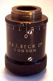 With the fitting of the right-angle prism to the microscope objective, and in the absence of the tubelength corrector, the imaging system is fixed focus. Moving the hand to and fro on the microscope stage is not sufficiently fast or flexible as a focus means, so some additional means must be provided.
A tubelength corrector (left) is an achromatic combination consisting of a positive element and a negative element with a knurled collar for varying the distance between them. An RMS standard objective thread at either end allows it to be inserted in the optical system between the objective and its normal seating at the lower end of the microscope body tube. The intended effect of this is to vary the distance in the microscope body tube at which the image-forming rays from the objective come to a focus. If this distance is fixed, the rapid action by which the elements of the tubelength corrector are separated becomes a rapid-action focus control for the imaging system, allowing sensitive variation of both system magnification and working distance. This arrangement allows focusing over a wider range than could be achieved by any purely mechanical focusing method, and works particularly well with very low power objectives. The range over which the tubelength corrector focuses is determined by the setting of the Meopta adjustable drawtube, which in this setup varies the distance between the eyepiece and the tubelength corrector. See the article on tubelength correctors (in preparation) for more detail. 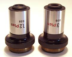 These objectives were produced by Nikon in the 1970s. They are planachromats,
and the optical design of both the x1.2/0.03 and x3/0.08 objectives is that of a Galilean telescope, having a strongly negative front element and a strongly positive rear element.
These objectives were produced by Nikon in the 1970s. They are planachromats,
and the optical design of both the x1.2/0.03 and x3/0.08 objectives is that of a Galilean telescope, having a strongly negative front element and a strongly positive rear element.
They require the use of a fairly strongly compensating eyepiece to give images free of colour fringing towards the edges of the field. They also have quite long working distances, and sufficient resolution for the task in hand, although those familiar with modern objectives which have higher NAs in proportion to their magnification would probably think them verging on the unsharp. If the same same film and optical components are used in the same configuration each time the equipment is used, and the flash units are set up at the same distance from the stage each time, there is no reason why exposure should vary. In this case, the only exposure variable is the distance of the flash units from the stage (or background paper). Even changing the low power for the high power objective will not alter the exposure, as the x3 objective has a larger NA (almost) in proportion to its increased magnification, and will therefore produce an image of equal brightness to that of the x1 objective. A series of test exposures with the flash units at different distances is therefore the simplest and most direct way of determining system exposure for the film in use. A fuller description of the considerations involved in determining flash exposures for the microscope will be found in the article Photomicrography using Electronic Flash.
|